

Strange behavior of quadcopter at boundaries
(Jul 17, 2015)
We recently performed the first test of our new rectangular bounding monitor. This runtime monitor is designed to prevent the quadcopter from violating any of the following bounds:
- an upper and lower bound on altitude
- a bound on how far the vehicle can go to the left and right
- upper and lower bounds on vertical velocity
- upper and lower bounds on left/right velocity
We formally verified, in Coq, that the quadcopter won’t violate any of these boundaries, no matter what the pilot or autopilot software does. This provides a really strong guarantee that our monitor does what it should. However, there is often a gap between the system that is verified and the system that actually runs, particularly for systems that interact with the physical world. Our test was a great example of this as we had a number of interesting problems. In this post, I’ll describe one of them.
The problem
We first noticed the problem when Sorin (who was piloting at the time), was manually holding the quadcopter at a constant altitude while trying to fly the quadcopter past the left boundary. The monitor was correctly preventing the vehicle from violating the left boundary. We wanted to make sure that the monitor would simultaneously enforce the left bound and altitude upper bound, so Sorin issued maximum throttle to the quadcopter while continuing to try to fly past the left boundary. However, instead of flying upward along the left boundary, the quadcopter suddenly fell straight downward. Sorin was too slow to turn off the monitor (we have a switch for that), and the quadcopter crashed (unfortunately, there’s no video of this).
This was a bit strange, since the monitor is designed to allow the vehicle to accelerate upward, even when the the pilot is attempting to violate the left or right bound. To add to the confusion, Sorin was able to move up and down on the left bound when he issued smaller throttles; it was only when he issued a large upward throttle that the vehicle fell downward.
The cause
As we later discovered, the cause of this strange behavior had to do with three things:
- The logic used by the monitor to determine whether to allow the pilot’s desired acceleration
- The default action used by the monitor when it detects a disallowed acceleration
- A gap between the model of the quadcopter that we verified and the physical quadcopter on which we run
In order to understand how these three components caused the problem, we have to take a look at the architecture of the quadcopter, outfitted with our monitor. The following images depict the architecture of the quadcopter, with and without our monitor, not including certain details that are irrelevant to this problem.
| Unmodified architecture | Architecture with our monitor |
|---|---|
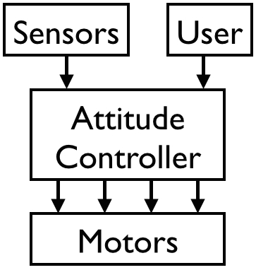 |
In the unmodifed architecture, the pilot issues a desired throttle, roll, pitch, and yaw to the existing attitude controller software. The attitude controller takes an estimate of the current state of the quadcopter (attitude, etc.) and uses this to compute signals to send to the four motors to achieve the pilot’s desired values. In the modifed architecture, our monitor intercepts the desired values from the pilot, and using the same state information from sensors, runs a safety check to determine whether the desired values will keep the quadcopter within bounds. If the safety check succeeds, the desired values are passed through unmodified; otherwise the monitor issues default safe values.
Our monitor assumes that the yaw is always 0, and it only enforces a
horizontal bound in the dimension corresponding to roll (left/right), so it
actually only cares about two input values from the pilot: a desired
throttle A and a desired roll angle Theta (0 corresponds to level
roll). The monitor first converts these polar acceleration coordinates into
rectangular coordinates, where X is the horizontal dimension and Z is the
vertical dimension:
AX = A*sin(Theta)
AZ = A*cos(Theta)
This simplifies verification since the safety check in the X and Z dimensions is the same. Using these rectangular accelerations, the monitor executes the following pseudo-code:
if (Safe(AX,...) && Safe(AZ,...)) {
  issue A and Theta
} else if (Safe(AZ,...) && ...) {
   issue polar(AZ, defaultX)
} else if (Safe(AX,...) && ...) {
   issue polar(defaultZ, AX)
} else {
   issue polar(defaultZ, defaultX)
}
The first branch is taken when the desired accelerations pass the monitor’s
safety check. In this case, the desired values are passed through
unmodified. The second branch is taken when the desired acceleration
projected in the Z (vertical) dimension is safe, but the X (left/right)
acceleration is not. There is an important additional condition there as
well, but more on that later. When the second branch is taken, the monitor
want to issue the desired Z acceleration (AZ) and a default safe
acceleration in the X dimension (defaultX). Since the monitor must
actually output a throttle and roll angle, it converts these new
rectangular acceleration coordinates back to polar. The third branch is
analogous to the second, with X and Z swapped. If the final branch is
taken, then default safe accelerations are issued for both the X and Z
dimensions.
Now we can return to the cause of the crash during the flight test. When the strange behavior occurred, Sorin was issuing desired values that would cause a violation of the left (X) boundary but not the upper bound on altitude (Z). One would then expect the second branch of the monitor to be taken. However, we need to take a closer look at the missing condition from that branch. The actual code is the following:
else if (Safe(AZ,...) && amin_z <= AZ <= amax_z) {
   issue polar(AZ, defaultX)
}
What are amin_z and amax_z? These are constant values that are
parameters to the monitor. They provide bounds on the breaking acceleration
that the monitor is allowed to issue when it needs to slow down to avoid
exceeding a position boundary. In other words, if the quadcopter is moving
quickly, is close to the upper bound on altitude, and the pilot issues
maximum upward throttle, the monitor can issue a Z acceleration of amin_z
in order to stop before the boundary.
It’s a bit weird that amin_z and amax_z appear in the conditional of
the branch where the desired Z acceleration is actually safe. There’s no
need to issue any breaking acceleration in the Z dimension, so why would we
care about its value? The reason is that amin_z, amax_z, amin_x, and
amax_x are carefully chosen so that any X and Z accelerations within
these ranges are physically achievable. Of course, any rectangular
coordinate can be converted to polar coordinates, so such a constraint
seems unnecessary. However, recall that our monitor outputs values to an
attitude controller. Our verification relies on the fact that this attitude
controller achieves the input attitude very quickly 1. This is only
possible within a limited roll angle range. Only a subset of the
rectangular accelerations are actually possible while respecting this
constraint on roll. Our breaking accelerations are chosen so that any
accelerations falling within amin_z, amax_z, amin_x, and amax_x are
within this subset.
Now recall that the crash occurred only when the quadcopter was on the left
boundary and Sorin issued a large desired upward acceleration. The issue
did not occur when Sorin issued only a small upward acceleration. A large
upward acceleration does not satisfy amin_z <= AZ <= amax_z, and thus the
monitor would take the fourth branch and issue default safe accelerations
in both the X and Z dimensions.
The final piece of the puzzle resides in the implementation of these default safe accelerations and the gap between model and reality. Since the quadcopter was hovering (zero vertical velocity) when Sorin issued the large upward acceleration, zero is a safe vertical acceleration, and this is in fact the monitor’s default action in that case. Zero acceleration while hovering should have resulted in more hovering, but instead the quadcopter dropped suddenly.
As it turns out this is due to the gap between the model we verify and the
actual running quadcopter. During this post, I’ve been treating throttle
and polar acceleration (A from above) interchangeably. In reality, they
are not the same thing, and for our actual quadcopter, we need to
experimentally determine the relationship between the two. On the day of
our first flight test, we forgot to do so. Instead, we used a default
relationship between the throttle and polar acceleration which happened to
work well in a simulator. This relationship greatly underestimated the
throttle required to actually achieve a particular acceleration, and thus
when the monitor issued a throttle that it intended to result in zero
vertical acceleration (countering gravity), it actually issued an throttle
resulting in a very negative vertical acceleration (much less than
gravity). The result was a crash and a very interesting lesson in practical
cyber-physical system verification.
-
In fact, we assume that the attitude controller achieves the input attitude instantaneously. This is a standard assumption made by control theorists if the attitude dynamics are significantly faster than velocity and position dynamics. ↩